Monday, March 4, 2024

I thought I lost this model!

It’s been almost a decade since I’ve posted anything here on iRevit.com and you have probably moved on from Revit and into Ai and didn't even know you were subscribed to this blog, but I had to share. I finally found the Revit model file of my Haueresque CW panel #5, which was inspired by Autodesk’s exhibition of Erwin Hauer’s sculptures which was organized by Tanja Dzambazova for Siigraph a while back… and had to 3D print it in case I lost it again! It looks awesome in physical form! 


You might recognize the model from the cover of Introducing Revit Architecture 2010

Cheers!

Tuesday, July 26, 2016

Converting Wall-based casework to Face-based in Revit

Recently there was a need for a custom piece of Revit family casework which was inadvertently made using a wall-based family template. I came across this post about switching lighting families from wall hosted to face-based and with a little tweak, made it work for casework.

This is how you do it.

1. Open up the family you need to convert to face based. Note the "Host" is currently set to "Wall" below.


2. Click on the "Family Categories and Parameters" button

3. Change the Category type to "Lighting Fixtures"
[We do this because the Copy-monitor function, which is a step in the process, only works on certain family categories]


4. Now, create a new project and load the family into it. Save the project as "Wall-hosted family.rvt"

5. Create another new project and link in the "Wall-hosted family.rvt" file.


6. On the Collaborate tab click "Copy Monitor" and "Select Link", and select the file you linked in.


7. Click the "Copy" Tool and select the Casework family, then click "Finish"


Ok, now here's the last part. 
8. Make sure the family isn't already open. Select the family now live in the project and click "Edit Family"


9. When the family opens up, click the "Family Categories and Parameters" button again to change the Category back to "Casework" and note that the Host is now set to "Face", woohoo!


10. Save your family file as an .RFA file in your library and you are done!
Trash the project files unless you've got more to convert. You can load multiple families into the project for this process if needed but you'll have to edit each one independently and save.


Cheers!


Wednesday, December 16, 2015

Revit 2016 Autodesk Raytracer: Rendered sections can include poche

Autodesk Raytracer render engine with Objects Styles "Cut" poche override

Mental Ray render engine with same Objects Styles override settings
Recently I was generating some marketing images of a specific project and thought I'd try the new render engine that Autodesk has added to Revit, the "Autodesk Raytracer". In the process I discovered something ...That the cut-poche overides in Object Styles are reflected in the rendering with this engine. Note the two renderings above. One is Mental Ray and the other is Autodesk Raytracer and both have essentially the same settings. This makes generating cool marketing and presentation images so much easier! Thank you, Autodesk. Strangely enough though is that the Autodesk-cloud-rendered images use still another render engine that does not reproduce this nice feature.
Close-up

Cheers!

Wednesday, March 18, 2015

Digital Tutors - Utilize Revit's tools to maximize your DESIGN WORKFLOWS

The latest lesson on Digital Tutors was just released. Digital Tutors is a great resource for professionals looking to learn a new tool or improve on their current skill-set.
In this series of Revit tutorials, I show you how to create several design options for an office lobby, explore the creation and use of Revit’s materials, and render a walk-through to understand the space.
I show you how to create and use specific design options to optimize your design workflow, as well as discuss the material assets library and create complex materials. I also show you how to set up advanced view types, talk about rendering options and create and edit walkthroughs.
By the end of this Revit training, you'll be more knowledgeable on how to maximize your potential with visualizations within Revit.

Thursday, January 29, 2015

Scan-to-BIM

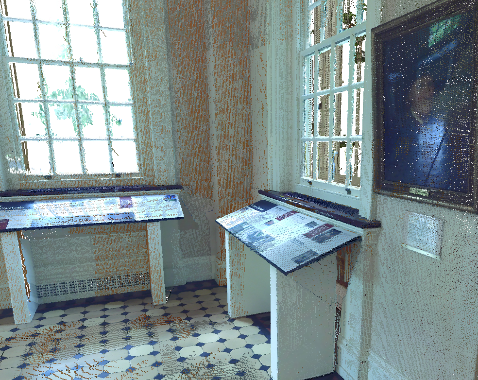
A portion of the laser scan point cloud loaded into Revit

A number of people have asked "What is Scan-to-BIM?" and so I take the opportunity here to showcase an exciting project as an example. 

In short, Scan-to-BIM is where we take a highly-accurate laser-scan of a space or building and build an existing conditions Revit model for use, reference, or archive. Why do this? Anyone who has had the experience of using a laser scan will likely tell you that they would never do it any other way going forward for several reasons.
  1. Accuracy - laser scanners such as the Faro Focus3D X 330 which I prefer are accurate to the fraction of a millimeter and can scan as close as 0.6m to as far as 330m. From experience I can tell you that people (of which I include myself) make mistakes, especially on surveys.
  2. Accessibility - sometimes it is difficult to measure high ceilings such as the Academy of Music. Laser scanning makes this a snap, including this information in the scan, as it not only scans great distances 360 degrees around, it also scans above.
  3. Speed - Scan duration, with standard scan resolution in b/w is approximately 2 minutes, and in color approximately 5 minutes, per scan "drop". A "drop" means each time the scanner is set down to scan. There were 4 scan drops for the main room seen below in Carpenter's Hall. Each took about 5 minutes which means in a span of 20 minutes we had a detailed measurable account of the entire space. If this were surveyed by hand, it would most likely mean going back to the project site to verify, and sometimes more than once, racking up hours and hours. Instead, it was short work. With a laser scan, if any measurement needed verification or a moulding profile like below is required, the information is available on demand with no need to revisit the site. 

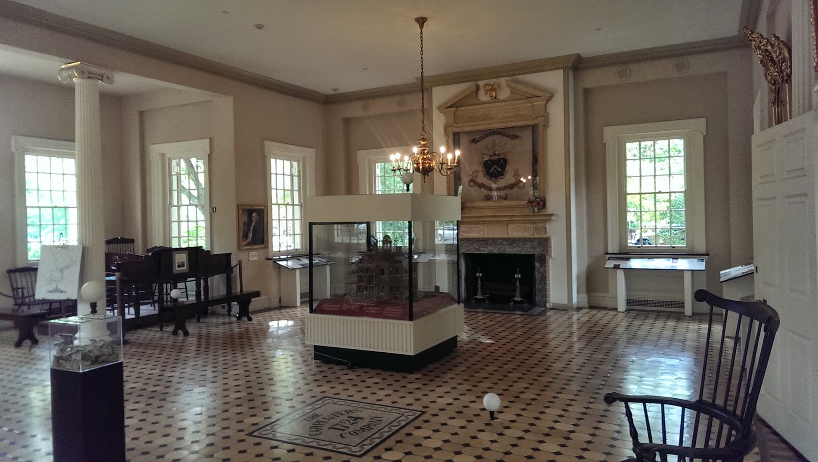
Photo of the main hall in Carpenter's Hall

With the scans complete, the Revit model could start and the process is fairly straight-forward. The raw scans are "Registered" (tied together accurately based on markers within the scan) using the Faro Scene software or Autodesk's Recap Pro, then linked into the Revit file using the "point cloud" button on the Insert tab.
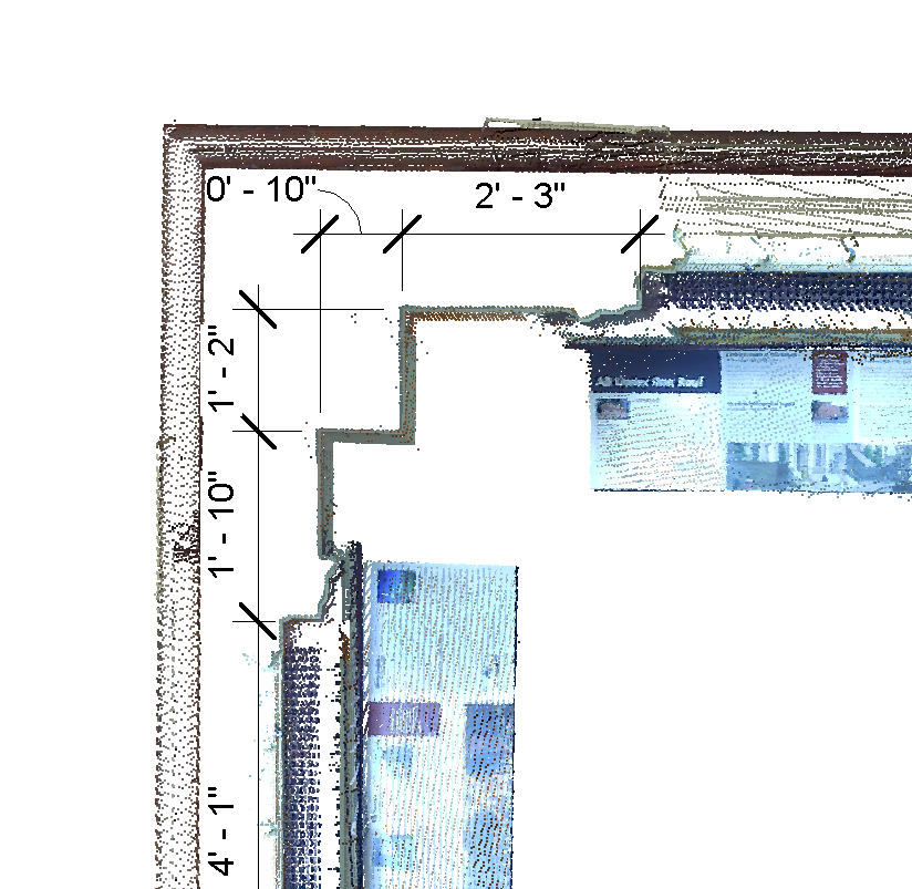
Detail of the point cloud in Revit showing dimensioning of the interior wall

Note that if you are working with a team in an office, you will want to place the scans in a network folder before inserting into Revit, otherwise, the other team members will not load the files correctly.

Note also that point clouds can be rather large files, often in the Gigabytes, so check with your IT group before clogging up your servers.
Detail of the door frame moulding and column fluting.

Building the Revit model is then fairly straight forward as well. You see the point cloud in the model space and then begin drawing walls, creating and placing elements until you have the level of detail required. One thing worth noting is that with exisitng buildings, you will find the walls and other building elements are not always plumb and often you'll find yourself questioning which point to select to begin drawing. My rule of thumb is to start with the middle-most or average point within the extremes, and to make your model plumb. This will result in some inconsistent overlap of the point cloud and your model but at the end of the day, if the project needs to be rebuilt, the plans will not want to have odd angles and measurements. On the other hand if the project is a renovation or retro-fit, then you might reconsider this. Regardless, you will have the point cloud which can be placed on the sheet as it is with any new construction modeled as a hybrid drawing.

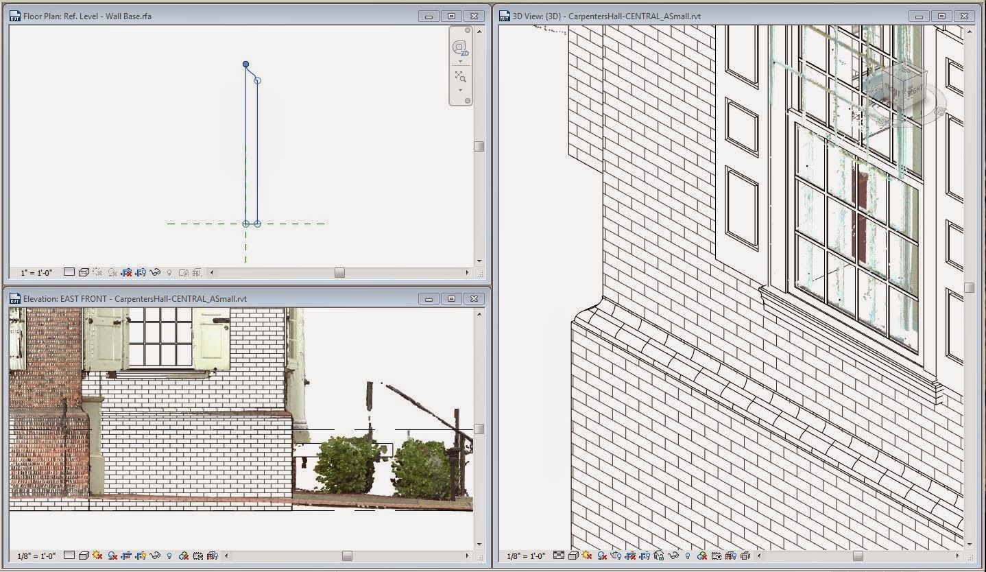
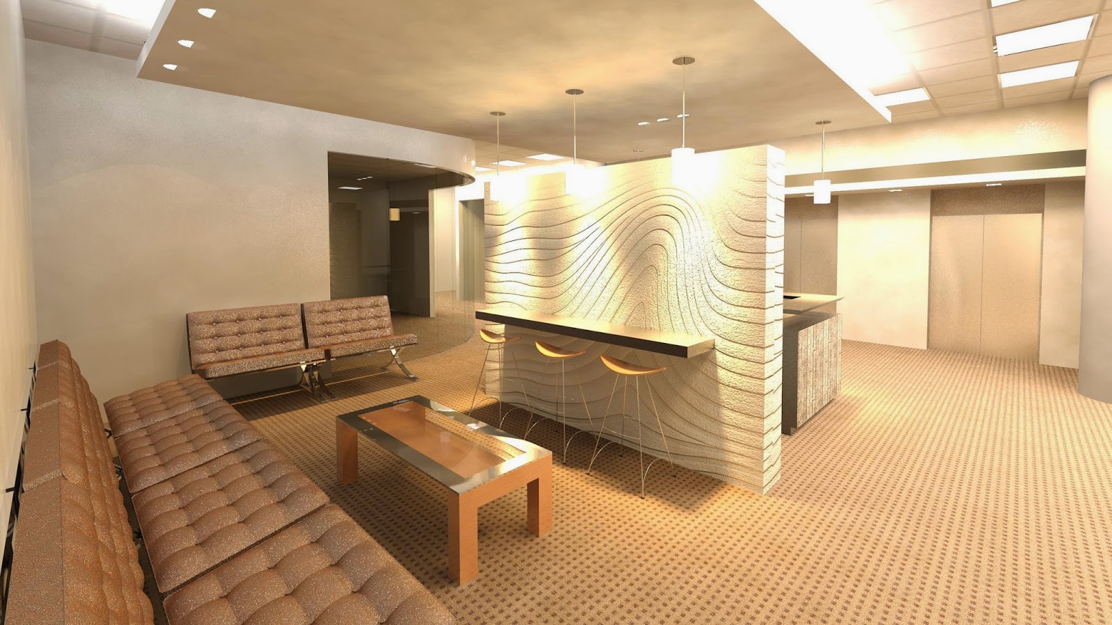
Screen capture of  the Revit working model
There are many other uses for laser scanning, Scan-to-BIM, and modeling, including construction monitoring, real estate transactions, building damage recording, monument protection, facilities management, accident re-creation, and much more.